the Molikpaq Platform
Design
During the early eighties Gulf Canada Resources were trying to solve the problem of building a mobile drilling platform for hydrocarbon exploration in about 30m of water, 100km north of Tuktoyaktuk in the offshore Arctic. The marine structural designer John Bruce conceived of a steel caisson with an annular hull, to be floated onto location, then ballasted down with sea water. To keep this vessel stable and on location while huge forces from the wind-driven polar ice-gyro pushed against it Hodge based his design on the simple shear box.
By pumping dredged sand into the open-bottomed core, friction between this fill and the granular berm could provide enough friction to withstand the multi-year ice. As the available sand was uniform with D50 = 0.35mm, and the ice load pulsated, Hodge's design called for densification of the lower half of the core as essential. This hybrid mobile caisson was named the Molikpaq.
In the winter of 1986, after several years deployment, the platform suffered excessive movement and associated settlement of the sandfill on the side facing the oncoming ice. It so happened the sandfill had not been densified as Hodge recommended - his design being overruled on the basis of centrifugal model work by others. So, as the severe ice loading reached the ultimate design capacity, core liquefaction was indicated, and the operation shut down. Because of environmental concerns, the regulatory authorities insisted that prior to redeployment the following year (1987), the sandfill must be densified as originally required.
Recovery
The job of sand-fill densification went to international competition as a lump-sum design-build contract. Phoenix™ Engineering Ltd won this contract. We went into the field prepared to approach the task either by detonating decks of explosive charges, or by using our proprietary Phoenix™ Machine hardware.
Custom designed drill-rigs were needed because the 72 metre square work space below deck had only 3.4m (11 feet) headroom.
As it turned out, charges detonated within 6m of the hull exceeded the structural limit of 330mm/s (13 inch/second) specified for vibrations at key steel members. This meant that the most critical area, the outer annulus around the core perimeter nearest the ice, could not be densified by blasting. The problem was solved by deploying the Phoenix™ Machine along a single line at 3m intervals in the middle of the 6m wide untreated annulus. Both arrays are shown on the plan of the inner core.
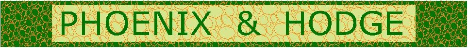
Results
These three CPT probes indicate the density increase achieved using a single line of Phoenix™ Machine treatments. The dark shading to the left is the post-blasting density which needed to be improved upon. The black trace is the CPT tip resistance record after using our hardware. The horizontal lines at 6.1m and 19.8m are the upper and lower limits between which treatment was activated. The set of three curves show relative density of 70%, 80% and 90%. The dimension "S" is the geometric mean distance from the CPT to the two closest treatment axes.
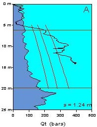
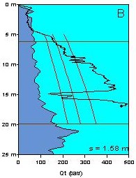
At CPT A the sandfill had been made so dense that the probe could not penetration past 14m. CPT B met refusal also, at 17m; the lack of substantial improvement around 15m is perhaps due to one rod length (1.5m) being inadvertently left untreated. The CPT C trace below 21m shows a return to ambient density beyond the treated depth; we do not have an explanation for the relatively poor performance deeper than 17m.
These three sounding represent the best results recorded, indicating relative densities in excess of 90% are achievable with the Phoenix™ Machine equipment. At some locations less impressive densities were indicated by the CPTs, and this in part is believed to be a consequence of the probe glancing off the top of the densified sand pillars below 4m, thereby causing the probe to drift from the treatment line into the body of the weaker, blasted, sandfill.